- 您现在的位置:买卖IC网 > Sheet目录2008 > MAX1183ECM+TD (Maxim Integrated Products)IC ADC 10BIT 40MSPS DL 48-TQFP
MAX1183
Dual 10-Bit, 40Msps, 3V, Low-Power ADC with
Internal Reference and Parallel Outputs
_______________________________________________________________________________________
9
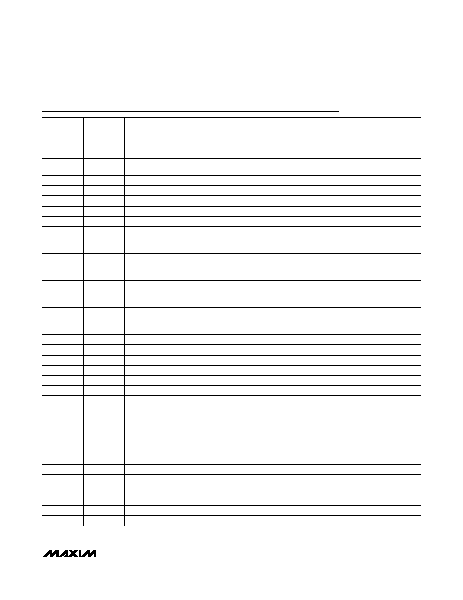
Pin Description
PIN
NAME
FUNCTION
1
COM
Common-Mode Voltage Input/Output. Bypass to GND with a
≥ 0.1F capacitor.
2, 6, 11,
14, 15
VDD
Analog Supply Voltage. Bypass each supply pin to GND with a 0.1F capacitor.
The analog supply accepts an input range of 2.7V to 3.6V.
3, 7, 10,
13, 16
GND
Analog Ground
4
INA+
Channel A Positive Analog Input. For single-ended operation connect signal source to INA+.
5
INA-
Channel A Negative Analog Input. For single-ended operation connect INA- to COM.
8
INB-
Channel B Negative Analog Input. For single-ended operation connect INB- to COM.
9
INB+
Channel B Positive Analog Input. For single-ended operation connect signal source to INB+.
12
CLK
Converter Clock Input
17
T/B
T/B selects the ADC digital output format.
High: Two’s complement.
Low: Straight offset binary.
18
SLEEP
Sleep Mode Input.
High: Deactivates the two ADCs, but leaves the reference bias circuit active.
Low: Normal operation.
19
PD
Power-Down Input.
High: Power-down mode.
Low: Normal operation.
20
OE
Output Enable Input.
High: Digital outputs disabled.
Low: Digital outputs enabled.
21
D9B
Three-State Digital Output, Bit 9 (MSB), Channel B
22
D8B
Three-State Digital Output, Bit 8, Channel B
23
D7B
Three-State Digital Output, Bit 7, Channel B
24
D6B
Three-State Digital Output, Bit 6, Channel B
25
D5B
Three-State Digital Output, Bit 5, Channel B
26
D4B
Three-State Digital Output, Bit 4, Channel B
27
D3B
Three-State Digital Output, Bit 3, Channel B
28
D2B
Three-State Digital Output, Bit 2, Channel B
29
D1B
Three-State Digital Output, Bit 1, Channel B
30
D0B
Three-State Digital Output, Bit 0 (LSB), Channel B
31, 34
OGND
Output Driver Ground
32, 33
OVDD
Output Driver Supply Voltage. Bypass each supply pin to OGND with a 0.1F capacitor.
The output driver supply accepts an input range of 1.7V to 3.6V.
35
D0A
Three-State Digital Output, Bit 0 (LSB), Channel A
36
D1A
Three-State Digital Output, Bit 1, Channel A
37
D2A
Three-State Digital Output, Bit 2, Channel A
38
D3A
Three-State Digital Output, Bit 3, Channel A
39
D4A
Three-State Digital Output, Bit 4, Channel A
40
D5A
Three-State Digital Output, Bit 5, Channel A
发布紧急采购,3分钟左右您将得到回复。
相关PDF资料
MAX1184ECM+TD
IC ADC 10BIT 20MSPS DL 48-TQFP
MAX1186ECM+TD
IC ADC 10BIT 40MSPS DL 48-TQFP
MAX1187CCUI+
IC ADC 16BIT 135KSPS 28-TSSOP
MAX118EAI+
IC ADC 8BIT 1MSPS 28-SSOP
MAX1191ETI+T
IC ADC 8BIT 7.5MSPS DL 28-TQFN
MAX1192ETI+T
IC ADC 8BIT 22MSPS DL 28-TQFN
MAX1195ECM+TD
IC ADC 8BIT 40MSPS DL 48-TQFP
MAX1197ECM+TD
IC ADC 8BIT 60MSPS DL 48-TQFP
相关代理商/技术参数
MAX1183ECM-D
功能描述:模数转换器 - ADC RoHS:否 制造商:Texas Instruments 通道数量:2 结构:Sigma-Delta 转换速率:125 SPs to 8 KSPs 分辨率:24 bit 输入类型:Differential 信噪比:107 dB 接口类型:SPI 工作电源电压:1.7 V to 3.6 V, 2.7 V to 5.25 V 最大工作温度:+ 85 C 安装风格:SMD/SMT 封装 / 箱体:VQFN-32
MAX1183ECM-TD
功能描述:模数转换器 - ADC RoHS:否 制造商:Texas Instruments 通道数量:2 结构:Sigma-Delta 转换速率:125 SPs to 8 KSPs 分辨率:24 bit 输入类型:Differential 信噪比:107 dB 接口类型:SPI 工作电源电压:1.7 V to 3.6 V, 2.7 V to 5.25 V 最大工作温度:+ 85 C 安装风格:SMD/SMT 封装 / 箱体:VQFN-32
MAX1184ECM
制造商:Maxim Integrated Products 功能描述:DUAL 10-BIT, 20MSPS, +3V, LOW-POWER ADC WITH - Rail/Tube
MAX1184ECM+D
功能描述:模数转换器 - ADC 10-Bit 2Ch 30Msps High Speed ADC RoHS:否 制造商:Texas Instruments 通道数量:2 结构:Sigma-Delta 转换速率:125 SPs to 8 KSPs 分辨率:24 bit 输入类型:Differential 信噪比:107 dB 接口类型:SPI 工作电源电压:1.7 V to 3.6 V, 2.7 V to 5.25 V 最大工作温度:+ 85 C 安装风格:SMD/SMT 封装 / 箱体:VQFN-32
MAX1184ECM+TD
功能描述:模数转换器 - ADC 10-Bit 2Ch 30Msps High Speed ADC RoHS:否 制造商:Texas Instruments 通道数量:2 结构:Sigma-Delta 转换速率:125 SPs to 8 KSPs 分辨率:24 bit 输入类型:Differential 信噪比:107 dB 接口类型:SPI 工作电源电压:1.7 V to 3.6 V, 2.7 V to 5.25 V 最大工作温度:+ 85 C 安装风格:SMD/SMT 封装 / 箱体:VQFN-32
MAX1184ECM-D
功能描述:模数转换器 - ADC RoHS:否 制造商:Texas Instruments 通道数量:2 结构:Sigma-Delta 转换速率:125 SPs to 8 KSPs 分辨率:24 bit 输入类型:Differential 信噪比:107 dB 接口类型:SPI 工作电源电压:1.7 V to 3.6 V, 2.7 V to 5.25 V 最大工作温度:+ 85 C 安装风格:SMD/SMT 封装 / 箱体:VQFN-32
MAX1184ECM-T
制造商:Maxim Integrated Products 功能描述:DUAL 10-BIT, 20MSPS, +3V, LOW-POWER ADC WITH - Tape and Reel
MAX1184ECM-TD
功能描述:模数转换器 - ADC RoHS:否 制造商:Texas Instruments 通道数量:2 结构:Sigma-Delta 转换速率:125 SPs to 8 KSPs 分辨率:24 bit 输入类型:Differential 信噪比:107 dB 接口类型:SPI 工作电源电压:1.7 V to 3.6 V, 2.7 V to 5.25 V 最大工作温度:+ 85 C 安装风格:SMD/SMT 封装 / 箱体:VQFN-32